
Developer Tools for Sketch Recognition User Interface Developers
Tracy Hammond & Randall Davis
Abstract
Sketch recognition systems are currently being developed for many domains, but can be time consuming to build if they are to handle the intricacies of each domain. The goal of our research is to make the development of a new sketch recognition user interface easier for the developer. Rather than build each recognition system separately, our group's philosophy is to have one recognition system that can be tailored for each domain. The developer is able to write a domain description in LADDER, which is then used to automatically generate a sketch recognition user interface for that domain.
To allow developers to automatically generate sketch recognition user interfaces (such as the one shown in Figure A), we have created 1) the LADDER, a language to describe how shapes in a domain are drawn, displayed, and edited [3], 2) a translator which transforms a domain description into domain specific recognizers, exhibitors, and editors, to be used by [2] 3) a general recognition system that uses lower level recognizers in combination with the generated recognizers to recognize neatly hand-drawn shapes in a domain. Because shape descriptions may be imperfect, we have also created a shape description debugger that corrects descriptions through an active learning process in which the system displays to the user computer generated suspected near miss examples [4].
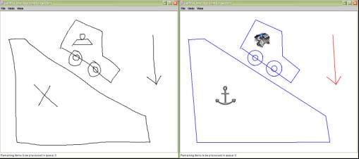
Figure A: Automatically Generated Sketch Recognition User Interface
for Mechanical Engineering
LADDER, a Sketching Language
LADDER allows interface designers to describe how shapes in a domain are drawn, displayed, and edited. An example arrow definition is shown on the left hand side of Figure B. The language consists of predefined shapes, constraints, editing behaviors, and display methods, as well as a syntax for specifying a domain description. The difficulty in creating such a language is ensuring that domain descriptions are easy to specify, and that the descriptions provide enough detail for accurate sketch recognition.
The language has proven powerful enough to describe shapes from several domains. The language supports both top down and bottom up recognition. Descriptions of how shapes may combine can aid in top down recognition and can be used to describe ``chain reaction" editing commands. To simplify the task of creating a domain description, shapes can be built hierarchically. LADDER descriptions are structural and primarily concern shape, but may include other information that is helpful to the recognition process, such as stroke order or stroke direction. The specification of editing behavior allows the system to determine when a pen gesture is intended to indicate editing rather than a stroke. Display information indicates what to display after strokes are recognized.
Recognition, Display and Editing in the User Interface
Figure B shows the system framework. The base customizable recognition system contains domain independent modules that can recognize, exhibit, and edit all of the primitive shapes in LADDER. These modules are noted by the shaded boxes without their inner white domain modules on the right side of Figure B.
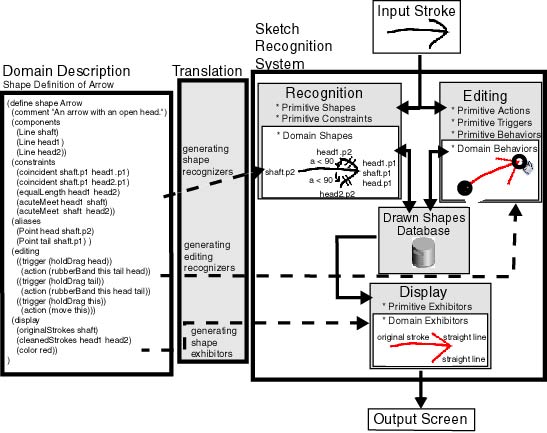
A drawn stroke is identified as either an editing gesture or a drawing gesture. If it is a drawing gesture, the strokes is classified as an Ellipse, Line, Curve, Arc, Point, Polyline or some combination using techniques by Sezgin [5]. In many cases the stroke is ambiguous and has more than one interpretation. When this happens both interpretations are produced and sent off to the higher level recognizer. If an editing gesture such as click-and-hold or double-click occurs, the system checks to see if the pen is over a shape and if the shape's description activated that editing trigger. If so, then the drawing gesture is short-circuited and the editing gesture takes over (for instance, the shape may then be dragged).
Recognition of domain shapes occurs as a series of bottom up opportunistic data driven triggers where the recognized shapes in the drawing represent the facts about the world. Domain shape recognition is performed by the Jess rule based system[1]. When a new shape primitive shape is recognized, it is added as a fact into the Jess rule-based system. Each domain shape recognizer is actually a Jess Rule automatically generated to recognize the shape. We created several additional Jess rules to perform higher level clean up on the shapes, such as merging lines together.
The shape description also specifies how each shape should be displayed (by its original strokes, best-fit primitives, the best fit primitives with all of the constraints solved -- the ideal shape, or through Java Swing objects) once it is recognized. The system uses Mathematica to solve the constraints if the developer has specified that the ideal shape should be displayed.
Debugging Shape Descriptions
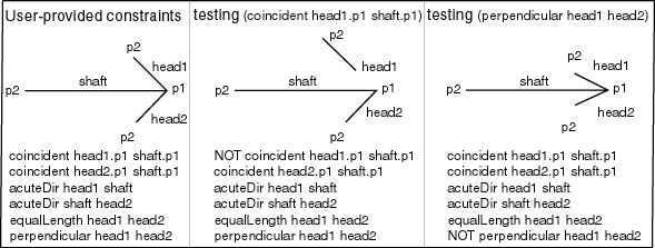
We perform active learning to perfect shape descriptions. However, since we have found humans to be unreliable at providing informative near miss examples, our active learning differs from traditional active learning in that we have the system generate the suspected near miss examples that are most informative to it. The system needs as input a positive drawn example and a starting description (which can be automatically generated [6] or manually typed). The system then automatically generates suspected near miss examples to debug over- or under-constrained shape descriptions. Figure C shows two generated shapes which test the coincident constraint followed by the perpendicular constraint. The developer specifies to the system if each generated shape is a positive or negative example of the shape she is trying to describe. They system then updates the descriptions to agree with positive and negative examples.
A possible near miss example shape is generated by creating a list of constraints (positive or negative) that should be true in the generated shape. These new constraints are then solved using Mathematica, making an effort to move segments of the hand drawn shape as little as possible (visually differing only in the constraint we are currently testing).
The Process
Here is an overview of the new process a developer would take to develop a sketch interface using our techniques. Note that this process is considerably faster than writing a complete recognition system from scratch.
- Developer makes a list of all of the shapes in the domain.
- Developer produces a description of all of the shapes in the domain
as follows:
- Developer draws an example shape
- The computer automatically generates a best-guess description (or the developer can chose to manual type one herself).
- The computer checks that the description is not over constrained,
for each constraint in the current description:
- The computer generates one suspected near miss example shape that tests if that constraint is required
- The developer specifies whether or not the shape is a valid example shape
- The computer uses this knowledge to include or remove the constraint
- The computer checks that the description is not under-constrained.
The computer generates a manageable (<20) number of constraints
that may be missing. For each possible new constraint:
- The computer generates one suspected near miss shape that tests if that constraint is required.
- The developer specifies whether or not the shape is a valid example shape
- The computer uses this knowlegde to include or remove the constraint
- The developer then manually specifies how the shape should be displayed and edited.
- Each description is then translated into a recognizer for that shape, and Java code specifying how the shape should be displayed and edited in automatically generated.
- The new code is compiled into a sketch recognition user interface for that domain.
- The sketch recognition user interface can be run and it will recognize, display, and allow editing of the shapes described in the description.
Conclusion
We have developed an innovative framework to aid developers in creating sketch recognition interfaces. We have created LADDER, a sketching language that allows developers to specify how to recognize, display, and edit shapes in a domain. We also created a multi-domain recognition system which takes as input a LADDER domain description, and then functions as a sketch recognition user interface for that domain. To simplify the creation of a domain description, we have created a graphical debugging tool for interface developers that corrects over- and under-constrained shape descriptions. The tool learns structural descriptions through active learning by presenting the user automatically generated suspected near-miss examples to refine the description.
Future Work
We are looking forward to integrating speech tags into the shape descriptions to aid recognition (link). Because it is likely that we would like to use are sketch recognition system as an alternate front end to a CAD system we would like to add a simple way to register for events.
References
[1]Ernest Friedman-Hill. Jess, the Java Expert System Shell. http://herzberg.ca.sandia.gov/jess, 2001.
[2]Tracy Hammond and Randall Davis. Automatically Transforming Symbolic Shape Descriptions for Use in Sketch Recognition. In The Nineteenth National Conference on Artifical Intelligence (AAAI-04), July 2004.
[3]Tracy Hammond and Randall Davis. LADDER: A Language to Describe Drawing, Display, and Editing in Sketch Recognition. In Proceedings of IJCAI (International Joint Conference on Artificial Intelligence), August 2003.
[4]Tracy Hammond and Randall Davis. Shady: A Shape Description Debugger for Use in Sketch Recognition, in AAAI Fall Symposium on Making Pen-Based Interaction Intelligent and Natural, October, 2004.
[5]Tevfik Metin Sezgin. Feature point detection and curve approximation for early processing in sketch recognition, Masters thesis, Massachusetts Institute of Technology, June 2001.
[6]Olya Veselova. Perceptually Based Learning of Shape Descriptions. Masters thesis, Massachusetts Institute of Technology, Cambridge, MA (2003).
The Stata Center, Building 32 - 32 Vassar Street - Cambridge, MA 02139 - USA tel:+1-617-253-0073 - publications@csail.mit.edu (Note: On July 1, 2003, the AI Lab and LCS merged to form CSAIL.) |