| Research Abstracts Home | CSAIL Digital Archive | Research Activities | CSAIL Home |
![]()
|
Research
Abstracts - 2007
|
|
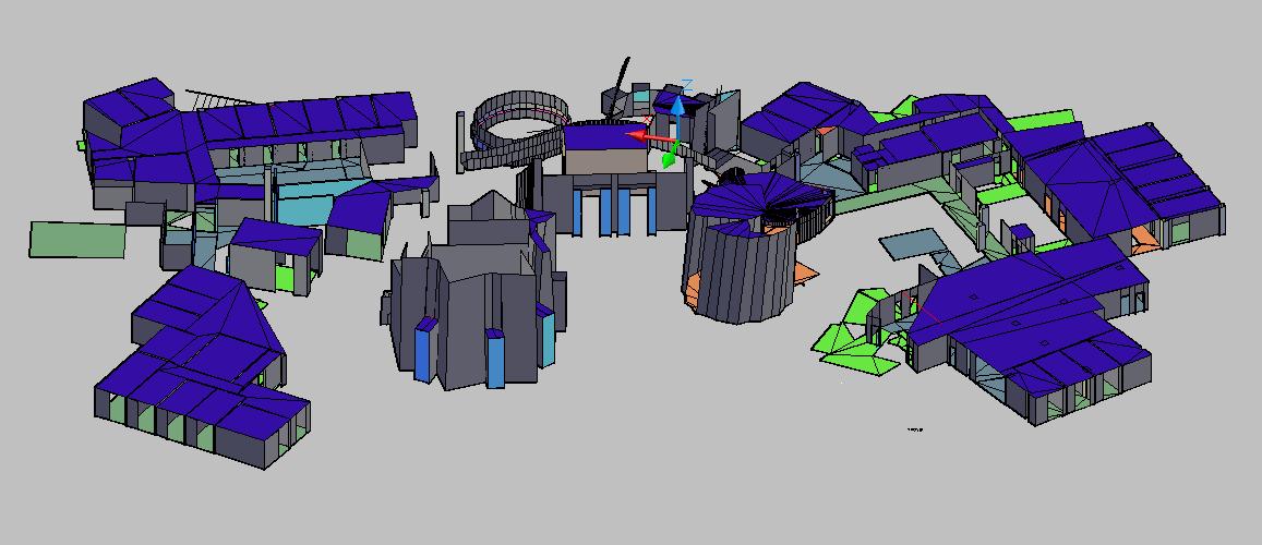
Ground-Truth, As-Built 3D CAD Model of Stata CenterXiao Xiao & Seth TellerIntroductionDuring summer 2006, we worked (along with a UROP, Tiffany Li) to construct an accurate, "as-built" 3D CAD model of the Stata Center. In fall 2006, Priscilla Graeff continued our work. We authored the model in AutoCAD 2007, using detailed 2D floorplans from the Department of Facilities as a starting point. Each source floorplan contains a 2D "slice" of each building floor, taken at a height of 48 inches from the actual floor. We made many field measurements with a Leica single-beam laser range finder and a measuring tape in order to correctly size and situate 3D elements such as walls, windows, floors, and ceilings. We used the measurements to extrude 3D model elements upward or downward from the 2D floorplans as appropriate. Moreover, we established a common 3D coordinate system throughout the building so that the separate 3D floorplans, when composed, would abut correctly. Finally, we wrote a number of convenience functions in AutoLISP to ease the repetitive work involved in modeling thousands of wall surfaces and other elements.
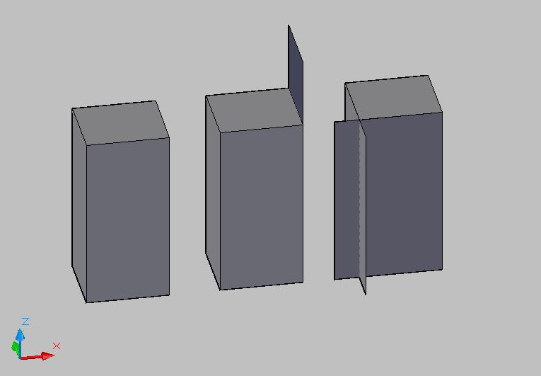
PurposeThere are many uses for a detailed, as-built 3D model of a building, especially one as complex as Stata. The model that we have built is useful for robotic mapping and vision-based localization research. A mapping robot can compare our model to its own generated map. A robot or sensor suite can take in our 3D model and use it as a means of localizing itself within an environment. The model can also be used for 3D visualization and simulated walkthroughs. PreliminariesThe 3D model of the Stata Center was constructed in order to satisfy certain properties. First, it must be manifold, which means that every edge in the model must be shared by exactly two faces, and must be used in opposing senses by those two faces. Therefore, the model must not have intersecting faces or faces that have edges not shared by other faces. In addition, the surface normal for every face (defined by the right-hand rule) must point toward the viewer. Thus when the viewer looks at the face, s/he will see the vertices occur in counter-clockwise order.
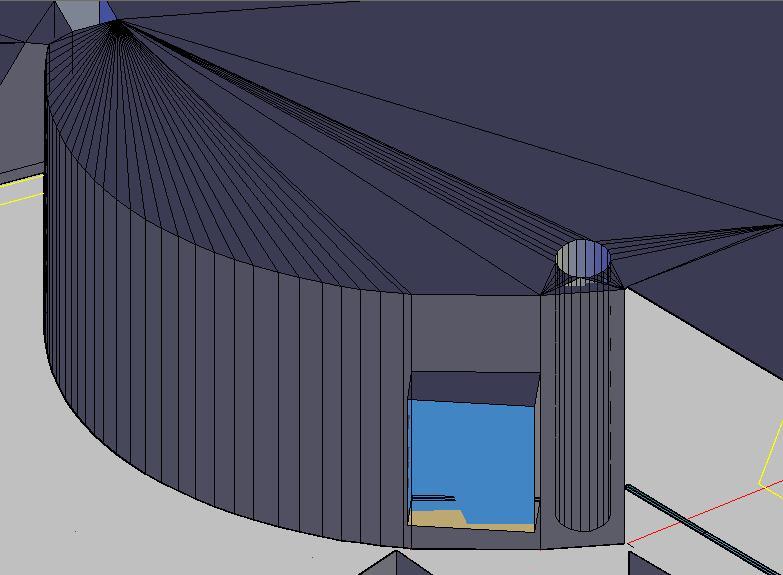
General ProcessWe used AutoCAD 2007 to author the 3D model. In AutoCAD, we modeled all surfaces as 3dfaces defined by three of four vertices. The way the surface normals point depends on the order these points are defined as discussed above. The AutoCAD DWG model can be converted into a more widely compatible format that can be viewed in various 3D viewers. To do that, we selected all the faces of our model, and used the LIST command within AutoCAD to obtain a list of all the selected elements, each with its properties. In this list, 3dfaces are written in terms of their vertices. This file is then fed through a C++ program written by Olivier Koch, which outputs 3 files --faces, edges, and vertices-- in a format that can be read by 3D viewers. ChallengesNon-Planar Walls Vertical non-planar walls are not much more difficult to model than vertical planar walls because they are nothing more than a series of narrow, planar walls. The non-vertical walls are drawn as polylines on the floorplan. To model them, we used the same wall function as the vertical planar walls and clicked on more points along the polylines. Floor and ceiling surfaces along non-planar walls are slightly more complicated than those along planar walls because they can no longer be divided into easy to model rectangles. We wrote a function that takes a vertex and a list of points, and draws many triangles emanating from the vertex. This function is useful in covering large areas with curved boundaries. To fill gaps, we modeled some faces by hand, taking care to respect the manifold constraints.
Non-Vertical elementsFor non-vertical, planar walls, we found the two endpoints of the wall on the ground by taking distance measurements from known points. Then, we plugged those points, the given floorplan points cut at 48 inch height, and the vertical height of the wall into a convex combination function, which computed the vertices of the slanted wall and instanced the wall as an AutoCAD object. Most of the time, the floor and/or ceiling traces are given for non-vertical, non-planar surfaces, so we could use them as a guide in drawing our walls. When both the floor and the ceiling traces are present, we used a function which took in a list of the top points and a list of the bottom points and drew walls connecting them. When we had two traces but not both the floor and the ceiling, we used a modified version of the convex combination function. |
|||
|