
| Research Abstracts Home | CSAIL Digital Archive | Research Activities | CSAIL Home |
![]()
|
Research
Abstracts - 2007
|
|
Distributed Multi-Robot Deployment Based on Successive Locally Optimal MatchingSeung-kook Yun & Daniela RusIntroductionCurrently, we are working on mobile robots which move only on a special structure: trusses (See Fig. 2). Each robot has two grippers and three joints for 3-d motion (See Fig.1). This robot is expected to move on the trusses and help construction of the structure in future. We need to develop a collaboration scheme for lots of robots on the same structure. Note that a robot can only move on the specific points on the trusses and every robot has the identical structure and functions. In addition, it must occupy at least one point to support itself. Our vision is to implement a manipulation task that requires co-operation of multi-robots in a distributed way. A moving tower built by several Shady3Ds and passive bars [1] is a good example of the possible tasks, although the robots in the simulation are precisely controlled by a central brain. We want to make it happen by the distributed robots, which have the identical hardware and software, and are capable of deciding its action without any help. We assume the same task of constructions is given to every robot 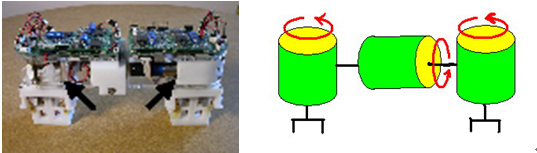 Fig.1 the mobile robot and its structure: 3-joints and 2 grippers [1] 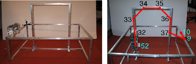 Fig.2 (a) truss structure and a robot (b) example: deployment of a single robot: numbers denote nodes on the trusses [1] As the first stage of realizing such a task, our goal is to deploy robots to the request points on the trusses in minimum number of total moves, implying minimal energy consumption. We need a collision-free min-cost path planning algorithm for multi-robots since a robot can not move through the other robot, as it turns out to make a big difference from a general matching algorithm in graph theory. Fortunately, the trusses can be modeled by a undirected graph, in which nodes are the specific points where a gripper of the robot can grasp and edges denote whether a robot can move between pairs of nodes. We will import a lot of useful theorems from the graph algorithm. Furthermore, the challenge is that we want a distributed algorithm. That is, we do not want a centralized controller which knows everything and controls all the robots. Instead, a robot has limited communication and sensing area, which is modeled by number of edges from the node occupied by the robot, and it must decide which way to go with the limited (sensed) information. Distributed Deploying Algorithm by Locally Optimal MatchingHere we propose our algorithm: distributed locally optimal matching in which each robot is continuously being reconfigured by heading to the locally optimal target node that is successively updated as it meets other robots which have already occupied its target node. To see the problem as a matching between Ri and Ti, which is a partial set of R and T which a robot i knows when it chooses the next target, we will introduce several selection criteria which deals with each case of the collision between two identical robots. Distributed algorithm based on Locally Optimal Matching between the initial nodes and the target nodesA. Internal resource In a distributed system, each robot has to decide its way based on information it has learned though the deployment. It also needs to share it via communication with other robots. Therefore, it should carry the required information for such a decision. The resources are following: ID: identification number Status: what it is doing now. Communicating, Idle, or Planning Settle Down: true if it has settled down at the target Pushing List: a list of the robots pushing a robot now, to check a cycle Location: currently occupying nodes by the anchor and the non-anchor gripper Initial and Target node matching list: a list of the initial and target nodes a robot has learned by the collisions only with settled-down robots Path to the target: a list of the nodes to the target from the current anchored node The details of how to use the resources are going to be explained in following sections. Note that an even centralized controller requires all the resources of all the robots to control them except for the Pushing List and matching list, since it has to be designed not to produce any collision. Therefore, the additional resources for a distributed controller are O(k) because the lists can include two times of the number of the robots in maximum. B. Deploying After the initialization, a controller executes an infinite loop as is in Algorithm 1. The loop is required because each robot is not capable of knowing whether all target nodes have their residency. This means it should be ready for another movement even after settling down at the target node, because it may start to move again by the collision as we will see in the following sections. In the loop, it repeatedly executes the Distributed Deployment algorithm in Algorithm 2, only if it is not communicating with the other robot. Then it waits a certain amount of time for possible communication. Note that receiving the communication cannot be processed at the same time with the planning, whereas requesting the communication can. Otherwise, the resources can be messed up by received data from the other one. 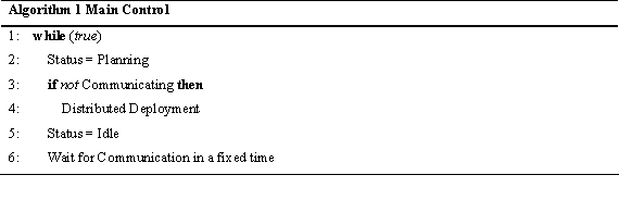 The Distributed Deployment algorithm is a main program, not only making a robot advance but also detecting a collision and handling it. First, the algorithm checks if this robot has already been located at the target where it is heading. If so, it sets the resource Settle Down as true, and ends the algorithm. If the robot has the remaining path to go though, it tries to communicate the other robots that may be around the first node of the path. Note that the system is set up so that a robot can only communicate with adjacent robots and only when the status of the robots is Idle. The purpose of the communication is to see if the others are already located at the next node or they are moving to it now. If the next node is empty, which means no robot is blocking this robot, and then a robot goes to the next node and updates the resources: it changes the location and makes the Pushing List null. Flushing the Pushing List is necessary because movement implies this robot does not belong to any cycle. 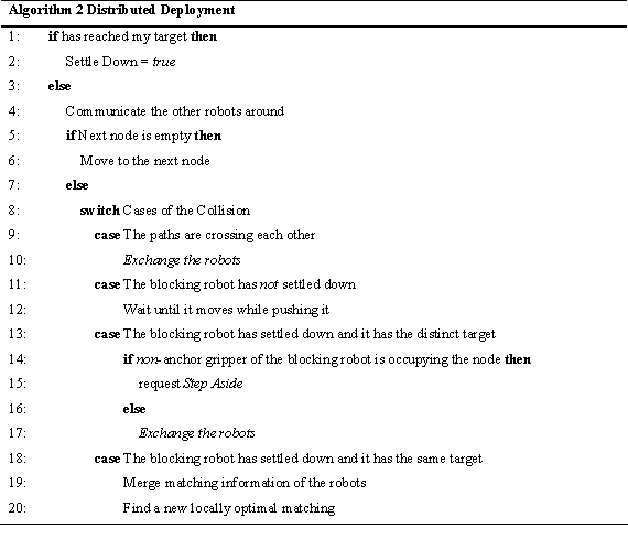 If the next node is occupied or being now, then the algorithm interprets in which category the collision is. Note that there can be five cases of the collision as shown in the algorithm. Then, it carries out the corresponding action. The details of the actions will be in the following sections. C. Cases of the collision between robots When the path of a robot and that of the blocking robot crosses each other, Exchanging the robots, which means to exchange all the resources, will prevent the collision as shown in Fig. 3(a) 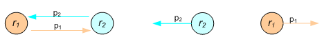 Fig. 3. Exchanging robots; r denotes a robot, and p does a path (a) two paths are crossing (b) after exchanging A deadlock is a status in which some robots can not move even though any paths of the robots are not crossed as shown in Fig. 4. To eliminate this deadlock, we exploit the Pushing List, which is composed of robots waiting for advance of the pushed robot. While communicating, a blocked robot sends its list to the blocking one so that the blocker can merge the list to its own one. Note that in a cycle, the communication sequence will make a circular link since they are adjacent by definition of the cycle. 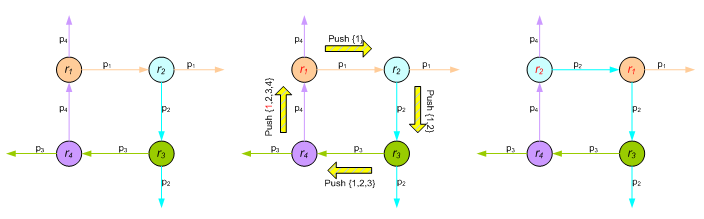 Fig. 4 How to break a deadlock (a) a deadlock (a cycle) happens (b) communication protocol for preventing the deadlock: push (c) the cycle is broken by exchanging identities. Unlike the other selection criteria, Stepping Aside is necessary because Shady3D has two grippers and occupies two nodes. Most of the proposed algorithms run based on the assumption that a robot is modeled as one point - an anchor gripper. In result, an unexpected collision, which does not appear in a system of the point-modeled robots, happens as shown in Fig. 5(a). The green one has settled down at the node occupied by the right gripper (anchor), and the blue one is trying to go through the node occupied by the non-anchor gripper of the green one. Even though the paths do not cross, there is no cycle and the two robots have the distinct targets, the blue one is stuck in a deadlock because the green one does not have a reason to move away. Therefore, under this specific condition, the blocked robot requests the stepping aside of the blocking one via communication so that it has an empty node to pass by, as shown in Fig 5(b). If there is no room for the non-anchor gripper to move to, the blocking robot notify this failure to the blocked one, and Exchanging the robots happens between them so that the blocked one advances instead of. 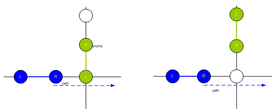 Fig.5. Stepping Aside: (a) the situation when the blue robot calls for a stepping aside of the green one (b) after the stepping aside of the green one The last selection criterion explains how to decide of a new target when a robot find the other one, blocking it, has the same target node. To solve this conflict, the blocked robot should find another target node, get a new path to it, and follow the path as it has done. D. Termination of the algorithm The last question is whether the process will terminate, when we define the termination as each robot has settled down on one of the targets. The answer is definitely yes. Whenever at least one robot is moving, the total distance between the robots and the target nodes is strictly decreasing because there is no deadlock. Therefore, if each robot has a distinct target node, which means a perfect matching, they will eventually reach one of them. By the selection criteria, each robot will surely have the distinct target at last, and this guarantees the perfect matching. Analysis of the Distributed Matching: Successively Finding the Local OptimumHere we explain the details of the proposed locally optimal matching and its performance compared with the global optimum. The algorithm is quite simple as shown in Algorithm 3. When a robot ¡®p¡¯ has found that the other ¡®q¡¯ occupied its target before it arrives, they merge their Matching list, {Rq, Tq} and {Rp, Tp}. Based on the merged Matching list and its starting node, it calculates the next target which is incident on the locally optimal matching Mp+q. We can efficiently obtain it by Hungarian algorithm[3] which has O(k3) runtime. Assume that each robot has the cost matrix C where Cij = cost of the shortest path from ri to tj.
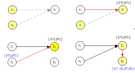 Fig. 6. Two robots are deploying according to the proposed matching algorithm: (a) initially, robot #1 and #2 have the same target node by the local optimal matching (b) Robot #1 arrives earlier than #2, and now it has its matching list [{r1}, {t1}]. (c) Robot #2 finds out t1 has already been occupied upon its arriving at t1. (d) Robot #2 gets a new target t2 by calculating the locally optimal matching with [{r1, r2}, {t1}]. After arriving t2, it updates the matching list by [{r1, r2}, {t1, t2}] It turns out that the proposed distributed deploying algorithm has O(k^2) asymptotical competitive ratio. Details can be found in our paper. Implementation: Simulation/ExperimentThe proposed distributed deployment algorithm has been implemented in simulation. Given a normal environment with the trusses, it turns out to produce surprisingly better results than the theory expected. The experiments are successfully performed to prove that the algorithm is working in the real world with a physical robot. A. Simulation To make sure the robots move in parallel, each one is simulated as independent process (thread). The target nodes and the initial nodes of the left and right grippers are randomly selected, and the left gripper is set as an anchor. We have tested two kinds of a map as a spare and dense graph. Although the dense one may not look dense enough to be a dense graph as does in graph theory, where edges outnumbers nodes, the shape is reasonable in a sense that the robots only move on the trusses where uniformly-spaced horizontal and vertical bars are in general. At each graph, 2~10 robots are simulated 100 times, respectively. The parameter of the fixed time to wait for the communication is set 0.1 second. Note that the less the time, the larger number of the communication and the less total execution time. The total time is defined as the spending time from the start of the simulation to where every robot settles down. Note that in a real distributed system, we cannot find the total time since there is no central controller.  The statistical results show up in Table 1. On both graphs, the average ratio of the cost by the distributed algorithm to that by the globally optimum is slowly proportional to the number of the robots, whereas the analytical worst bound increases in a quadratic fashion. Even with 10 robots, the ratio is only around two, and it appears that a type of the graph does not affect it. As for the average number of communication per robot, defined as dividing the total number by two times of the robot number where the constant two implicates mutual nature of communication, the sparse graph gives larger ones. This is reasonable in a sense that a robot tends to have more chances to collide with the others on a sparse graph where there are not many detours. B. Experiment The proposed algorithm has been implemented in a real hardware where consists of two real Shady3D, two fake robots, and a simple truss structure as shown in Fig. 7. Shady3D communicates via Bluetooth receivers, and in order to satisfy the assumptions, its range is purposely pretended as if it senses only one-edge distance from the anchor node. Because Shady3D is still under development, a main controller is located in a personal computer. Therefore, the system is not strictly distributed, however, the main controller is designed to ensures that each robot behaves as if it is fully distributed. On the other hand, the fake robots are introduced because we do not have many robot hardware. They are manually controlled and simulated by the main computer as if they move and even communicate by themselves. 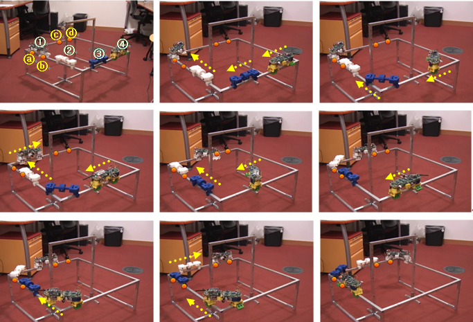 ConclusionWe introduce a modular mobile manipulator Shady3D, which works on the trusses. To realize the modularity, we propose a new distributed deployment algorithm based on successive locally optimal matching, which is a perfect min-cost bipartite matching between the initial nodes and the target nodes that a robot has learned through the collisions. In addition to that, we handle the cases of the collision by the proper selection criteria. Not only we have found a feasible solution, but also the optimality has been proven a quadratic. The algorithm has O(k2) competitive ratio while a simple greedy gives an exponential one. We have also analyzed that it has O(k^4+ k (n+m) log n) runtime while the offline global optimum has O(k(k^2+n+m) log (n+ k^2)). In the simulations, we have found out the algorithm works very efficiently in a view of the cost and the communication. Finally, we applied it to the real system with Shady3Ds and some fake robots, and this confirms the functionality of the algorithm. As we mentioned earlier, the work in this paper is considered as the first stage of a distributed construction in our vision. In future, we will implement manipulation work executed by multi-Shady3Ds. We are going to make a 6-dof manipulator out of two Shady3Ds and control them in a unified control approach as we did for a single robot. We hope it will work in a distributed way as the deployment algorithm does, and these two phases will be combined together. References:[1] Yeoreum Yoon. Title of the paper. Modular Robots for Making and Climbing 3-D Trusses, MS Thesis, CSAIL, MIT, 2006 [2] Zack Butler and Daniela Rus. Distributed Planning and Control for Modular Robots with Unit-Compressible Modules, The International Journal of Robotics Research, 22(9):699-715, 2003 [3] H.W. Kuhn. The Hungarian method for the assignment problem. Naval Res. Logist. Quart., 2, pp.83-97, 1955 |
|||
|